

This view allows you to communicate with your local XBee module over the serial interface.
Layout
The XBee Console view is organized into the following main areas:
Toolbar
Located at the top of the view, it contains the following elements:

-
Open/Close connection button: Toggles the connection state between connected and disconnected.
By default, it is disconnected.
-
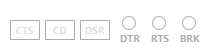
Serial port line status indicator: Displays the status of the RS-232 hardware flow control lines.
Green indicates an asserted line, while white indicates a de-asserted line.
You must open the console connection to display the line status and enable the line status control.
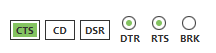
You can view and manage the following lines from the line status indicator:
Line ID Line name Description CTS
Clear to send
Indicates that the connected device is ready to accept data.
CD
Carrier detect
Detects the presence of connection.
DSR
Data set ready
Indicates that the connected device is ready for communication.
DTR
Data terminal ready
Indicates that the terminal is ready for communication.
RTS
Ready to send
Requests that the connected device prepare to receive data.
BRK
Break
Engages the serial line break. Asserting this line places the
DIline high, preventing data from being sent to the radio. -
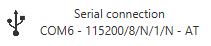
Connection indicator: Shows connection details.
Depending on the connection type, this information includes:
-
The icon of a serial connection, the port name, and the rest of the serial port parameters of the connection and operating mode of the device.
-
The icon of a Digi Remote Manager® connection, the Digi Remote Manager® account the device is registered into, and the Device ID of the device.

-
Console log
This is the main section of the view.
By default, the console log is disabled until a connection with the device is established. Once connected, the console becomes active and the caret starts blinking.
In the top-right corner you can see the following buttons:
| Button | Name | Description |
|---|---|---|
|
Load console session |
Imports a console session |
|
Save console session |
Saves the sent and received data from the current console session. With this feature, both raw data and API frames are exported to a |
|
Scroll lock |
Enables/disables the scroll lock functionality of the console log control. |
|
Clear log |
Erases the contents of the console log. |
Send data control
Expandable panel that slides up when clicked, displaying the controls used to create and reorder raw data packets or API frames to be sent to the current device.
Click it again to collapse the panel and hide its contents.

-
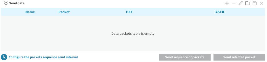
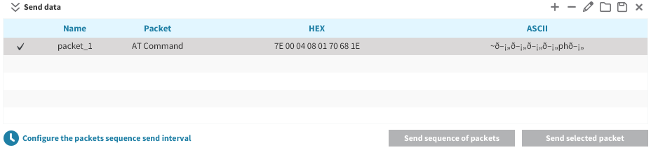
Data packets table: Displays the raw data packets or API frames to be sent to the current device.
You can select one or more packets from the table and send them at any time.
Each row represents a packet and includes a Sequence checkbox in the first column to mark the packets that belong to the send sequence. The last column contains a Send button (
 ) to transmit that specific packet individually.
A set of buttons in the top-right corner allows you to manage the table contents:
Button Name Description 
Add new packet
Adds a new raw data packet or API frame to the list.

Remove selected packet
Deletes the selected packet from the table.

Edit selected packet
Edits the name or contents of the selected packet.

Load packets list
Imports a previously saved list of packets.

Save packets list
Exports the current list of packets for future sessions or for use on another computer.

Clear packets list
Removes all packets from the table.
-
Send sequence (x/y) button: Sends all packets marked in the Sequence column, in the order they appear in the table. The label indicates how many packets are selected (
x) out of the total number of packets in the table (y). This button is enabled only when at least one packet or API frame is part of the sequence. -
Configure the packets sequence send interval button: Opens a popup that allows you to configure how the packet sequence is sent. It contains the following fields:
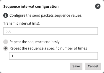
-
Transmit interval: Defines the amount of time to wait between each packet transmission. The default value is 500 ms.
-
Repeat sequence: Lets you choose whether to repeat the sequence continuously or a specific number of times. By default, the sequence is sent only once.
-
Start a console session
By default, when you first open the device console, it is disconnected. This is indicated by the gray background of the console log and the disabled serial port status indicator.
-
Click Open to establish communication with the device.
After the connection is established, the button icon changes to the connected state and the serial port status line and the console log controls are enabled.
-
At this point, all incoming data packets or API frames, if any, are captured and displayed in the console log control.
Inspect the console log data
Once the connection is established, all incoming data is logged in the console log. The log displays both raw data and API frames in the same view.
-
If data is raw, for example, when working in command mode with the device or sending or receiving data when the device is in AT mode, it is displayed as follows:
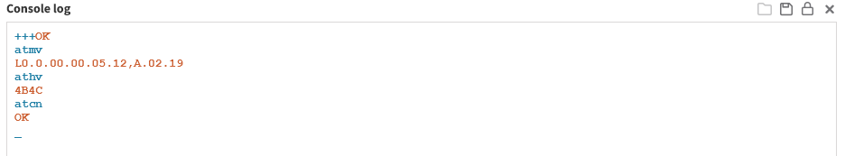
-
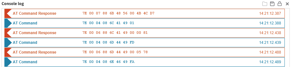
And if data comes in frame format, for instance, when working in API or API2 modes, each frame is represented as a box containing the frame type, the content of the frame in hexadecimal format and the time when it was logged:
This view is the same for both types of packets—raw or API frames. For example, if your module is working in API mode but you were configuring it or reading data using command mode when a packet arrives or when you decide to send a frame, it all gets represented without changing the view:
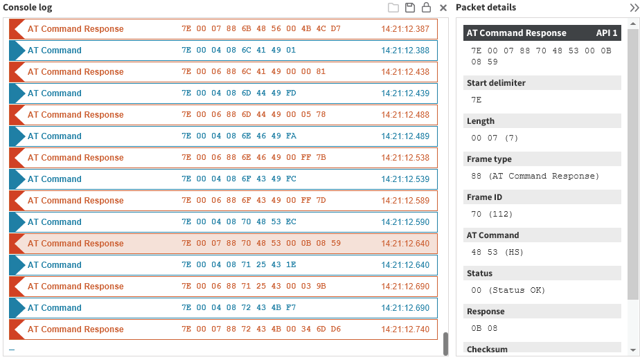
Also, you can see the decoded content of each frame by clicking on it. When you click on a frame box, the packet details viewer slides in from the right to occupy part of the layout. This allows you to see the console log while inspecting each packet individually.
Send packets
The type of packet you can create and send depends on the operating mode of your device.
You can send data byte by byte, or you can send a set of bytes—a data packet. To send a data packet, you must first create one. By default, the data packets list is empty.
-
Click the Send data section to expand it.
-
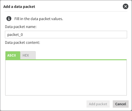
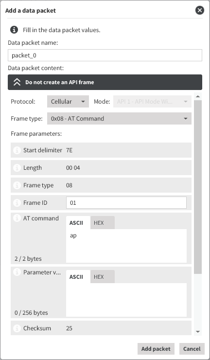
Click Add new packet in the Send data section. The Add a data packet popup appears:
-
Enter the name of the data packet to be added to the list.
-
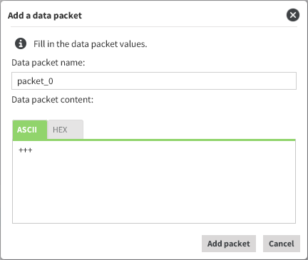
Paste or type in your data. You can use the tabs to toggle between ASCII and HEX input views.
-
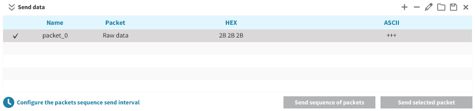
Click Add packet. The popup is closed and the data packet appears in the table of packets.
Repeat the process to add more packets to the list.
-
When finished, you can send a single packet or a sequence of packets.
You can send data in an API frame. An API frame is the structured data sent and received through the serial interface of the radio module when it is configured in API or API escaped operating modes. API frames are used to communicate with the module or with other modules in the network. To send an API frame, you must first create one.
-
Click the Send data section to expand it.
-
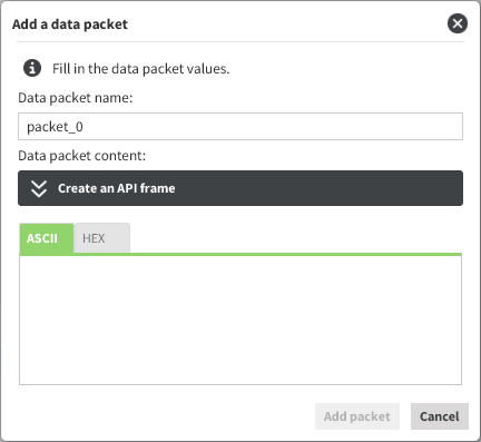
Click Add new packet in the Send data section. The Add a data packet popup appears:
-
Enter the name of the frame to be added to the list.
-
Create a frame by doing one of the following:
-
Paste or type in the byte array of the API frame.
-
Use the API frames generator functionality:
-
Click Create an API frame to expand the API frames generator control.
-
Fill out the required fields to generate the frame.
-
-
-
Click Add packet. The popup is closed and the API frame appears in the table of packets. Repeat the operation to add additional frames to the list.
-
When finished, you can send a single frame or a sequence of frames.