

The i.MX95 SoC provides:
-
Two Camera Sensor Interface (CSI) modules (one of them shared with MIPI DSI)
-
Image Signal Processing (ISP) on the camera stream
Available camera interfaces
On the ConnectCore 95 SMT SOM:
-
The two MIPI CSI-2 module lines are available on the LGA pads:
-
MIPI CSI1 (4 lanes available).
-
MIPI DSICSI1 (4 lanes available). This interface is multiplexed with MIPI DSI (both cannot be used at the same time).
-
On the ConnectCore 95 SMARC SOM:
-
Four lanes of the first MIPI CSI-2 module are routed to
CSI1interface of the SMARC connector. -
Four lanes of the second MIPI CSI-2 module (multiplexed with MIPI DSI) are routed to the SMARC connector as follows:
-
DATA0andDATA1lanes are routed toCSI0_RX0andCSI0_RX1lanes of the SMARC connector. -
DATA2andDATA3lanes are routed toHDMI_D1andHDMI_D2lanes of the SMARC connector.
-
On the ConnectCore 95 Development Kit:
-
CSI1interface of the SMARC connector is routed to:-
A 22-pin MIPI CSI-2 FFC connector (4 data lanes)
-
A 15-pin MIPI CSI-2 FFC connector (2 data lanes)
-
Camera connection
The BSP includes support for:
-
Digilent Pcam 5C MIPI camera (Omnivision OV5640 sensor)
-
NXP EXPI-OS08A20 camera (Omnivision OS08A20 sensor)
Connect Digilent Pcam 5C MIPI camera
|
Ensure that the correct cable is used and properly oriented when connecting the MIPI camera to the ConnectCore 95 Development Kit. Incorrect cable selection or improper orientation may cause permanent damage to the camera. |
For ConnectCore 95 Development Kit, use a 15 pin, 1mm pitch FFC cable with contacts on bottom on both sides. Pin 1 of the ConnectCore 95 Development Kit connector aligns with pin 1 of the camera connector.

Connect NXP EXPI-OS08A20 camera
|
Ensure that the correct cable is used and properly oriented when connecting the MIPI camera to the ConnectCore 95 Development Kit. Incorrect cable selection or improper orientation may cause permanent damage to the camera. |
For ConnectCore 95 Development Kit, use a 22 pin, 0.5mm pitch FFC cable with contacts on bottom on both sides. Pin 1 of the ConnectCore 95 Development Kit connector aligns with pin 1 of the camera connector.

Kernel configuration
You can manage the CSI driver support and Video4Linux (V4L2) capture driver through the following kernel configuration options:
-
NXP i.MX95 CSI Pixel Formatter Driver (
CONFIG_VIDEO_IMX_CSI_FORMATTER) -
NXP NEO ISP v4l2 hardware driver (
CONFIG_VIDEO_NXP_NEOISP) -
Freescale i.MX9 DPHY Rx (
CONFIG_PHY_FSL_IMX9_DPHY_RX) -
DesignWare Cores MIPI CSI-2 receiver found on i.MX93 (
CONFIG_VIDEO_DWC_MIPI_CSIS) -
OmniVision OV5640 sensor support (
CONFIG_VIDEO_OV5640) -
OmniVision raw sensor support OX05B1S (
CONFIG_VIDEO_OX05B1S)
These options are enabled as built-in on the default ConnectCore 95 kernel configuration file.
Kernel driver
The drivers for CSI capture are located at:
| File | Description |
|---|---|
NXP i.MX95 CSI Pixel Formatter Driver |
|
NXP NEO ISP v4l2 hardware driver |
|
Freescale i.MX9 DPHY Rx |
|
DesignWare Cores MIPI CSI-2 receiver found on i.MX93 |
|
Image Sensing Interface driver |
|
OmniVision OV5640 sensor support |
|
OmniVision raw sensor support OX05B1S |
Device tree bindings and customization
Digi provides two pre-compiled device tree overlays, so that you can test the camera interface without needing to recompile a device tree:
-
Digilent Pcam 5C MIPI camera in
arch/arm64/boot/dts/digi/ccimx95-dvk_pcam5c.dtso. -
NXP EXPI-OS08A20 camera in
arch/arm64/boot/dts/digi/ccimx95-dvk_expi-os08a20-cam.dtso.
The device tree overlays provide a reference implementation that:
-
Declares the camera sensor.
-
Enables the MIPI CSI components (MIPI port, pixel formatter, ISI, ISP).
-
Configures the IOMUX (if any CPU GPIO is required).
To enable a camera device tree overlay, append the overlay to the overlays environment variable in U-Boot, for example:
=> setenv overlays ccimx95-dvk_expi-os08a20-cam.dtbo,${overlays}See Device tree files and overlays for more information.
Use the camera
Use the NXP EXPI-OS08A20 camera
The NXP EXPI-OS08A20 camera uses the libcamera framework directly, so no manual media link configuration is required.
Configure the camera
Before using the camera, configure libcamera to prioritize the NXP Neo ISP pipeline:
# export LIBCAMERA_PIPELINES_MATCH_LIST='nxp/neo,imx8-isi,simple'Preview a camera image using gstreamer
# gst-launch-1.0 libcamerasrc ! video/x-raw,format=YUY2 ! queue ! waylandsinkTake a picture with the camera using gstreamer
# gst-launch-1.0 -e libcamerasrc src::stream-role=still-capture ! video/x-raw,width=1920,height=1080,format=NV12 ! identity eos-after=5 ! jpegenc ! multifilesink location=sample.jpg max-files=1| The command takes five frames but only saves the last. Discarding the first four eliminates undesired frames on cameras that have auto-exposure. |
To show the captured image using gstreamer:
# gst-launch-1.0 filesrc location=sample.jpg ! jpegdec ! imagefreeze ! waylandsinkYou can also show the captured image with:
# weston-image sample.jpgRecord a video with the camera using gstreamer
# timeout -s INT 10 gst-launch-1.0 -e libcamerasrc src::stream-role=video-recording ! video/x-raw,width=1920,height=1080,format=NV12 ! videoconvert ! queue ! v4l2h264enc ! h264parse ! mp4mux ! filesink location=sample.mp4To play the recorded video:
# gplay-1.0 sample.mp4Use the Digilent Pcam 5C MIPI camera
The Digilent Pcam 5C MIPI camera requires manual media link configuration before capture.
Identify the camera capture devices
Camera configuration and operation is divided between several interconnected subdevices, called entities, sharing video data.
You can use the media-ctl tool to obtain the full camera subsystem topology, a list of subdevices, the connections between them, and some additional postprocessing operations that can be performed on the fly such as cropping or downscaling:
# media-ctl -p
Media controller API version 6.6.52

Media device information
------------------------
driver          neoisp
model           neoisp
serial
bus info        platform:4ae00000.isp
hw revision     0x2
driver version  6.6.52

Device topology
- entity 1: neoisp (6 pads, 6 links, 0 routes)
            type V4L2 subdev subtype Unknown flags 0
            device node name /dev/v4l-subdev0
        pad0: Sink
                <- "neoisp-input0":0 [ENABLED,IMMUTABLE]
        pad1: Sink
                <- "neoisp-input1":0 []
        pad2: Sink
                <- "neoisp-params":0 [ENABLED]
        pad3: Source
                -> "neoisp-frame":0 [ENABLED]
        pad4: Source
                -> "neoisp-ir":0 []
        pad5: Source
                -> "neoisp-stats":0 [ENABLED]


	[...]


- entity 38: neoisp-stats (1 pad, 1 link)
             type Node subtype V4L flags 0
             device node name /dev/video16
        pad0: Sink
                <- "neoisp":5 [ENABLED]
Alternatively, you can create a dot graph using the same tool to have a visual representation of the whole camera subsystem:
# media-ctl --print-dot > graph.dotUse your host PC to convert the graph.dot file to a PNG image:
$ dot -Tpng -Nfontname=Roboto -Nfontsize=10 -Efontname=Roboto -Efontsize=10 graph.dot > graph.png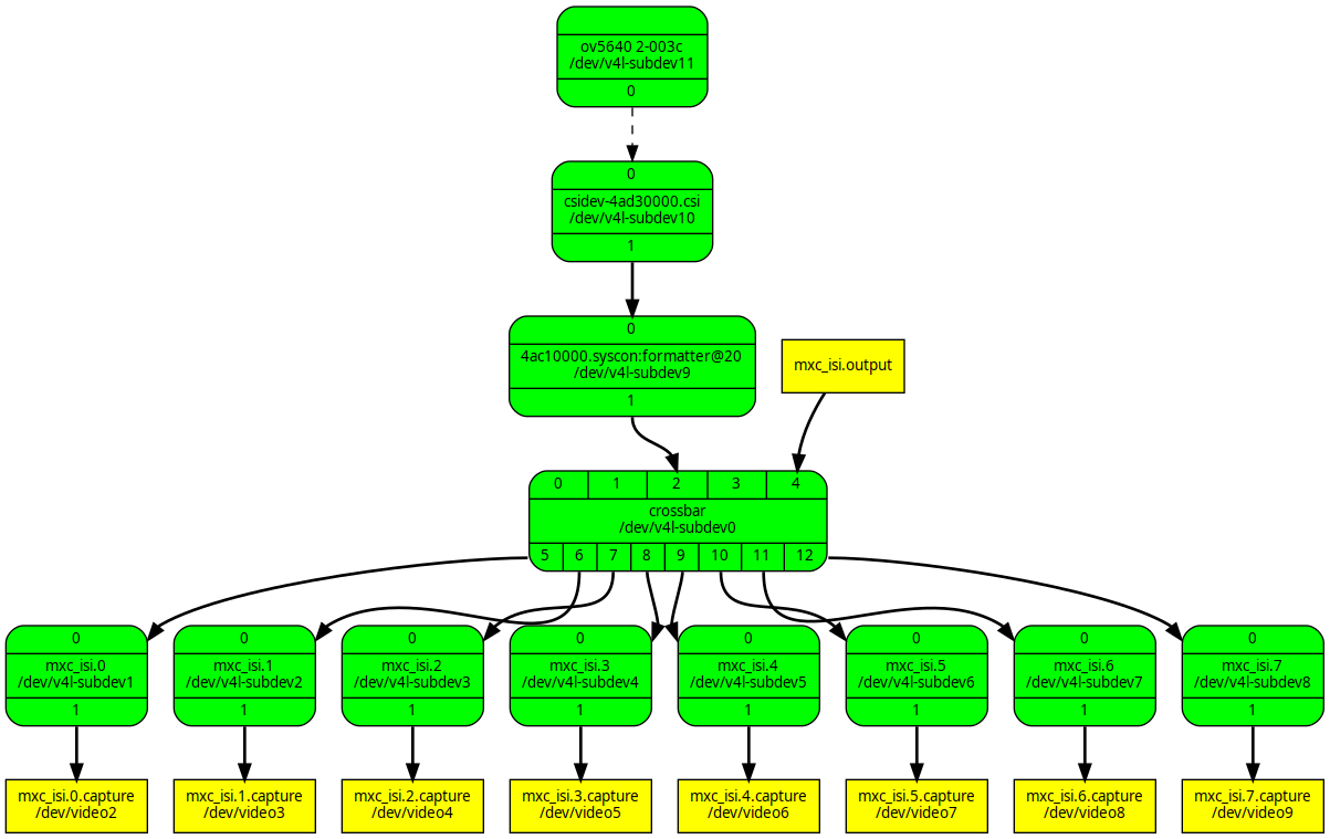
This graph, generated by the media-ctl tool, shows the different video pipes the data can flow through, from the camera sensor on the top (source) to the Linux video devices on the bottom (sink).
Configure the media links
| This step is required before you run any capture with the camera. |
Configure the video path that will flow from the camera sensor to the Linux video devices with the desired resolution and format.
-
Reset all media links
# media-ctl -r -
Set a local variable
FORMATwith format and resolution (in this example, raw video at 1280x720):# FORMAT=UYVY8_1X16/1280x720 -
Establish links between the media entities and configure the format and frame size they will operate at:
# media-ctl -d platform:4ad50000.isi -l '"ov5640 2-003c":0->"csidev-4ad30000.csi":0 [1]'
# media-ctl -d platform:4ad50000.isi -l '"csidev-4ad30000.csi":1->"4ac10000.syscon:formatter@20":0 [1]'
# media-ctl -d platform:4ad50000.isi --set-v4l2 "'ov5640 2-003c':0[fmt:${FORMAT} field:none]"
# media-ctl -d platform:4ad50000.isi --set-v4l2 "'csidev-4ad30000.csi':0 [fmt:${FORMAT} field:none]"
# media-ctl -d platform:4ad50000.isi --set-v4l2 "'4ac10000.syscon:formatter@20':0 [fmt:${FORMAT} field:none]"
# media-ctl -d platform:4ad50000.isi --set-v4l2 "'crossbar':2 [fmt:${FORMAT} field:none]"
# media-ctl -d platform:4ad50000.isi --set-v4l2 "'mxc_isi.0':0 [fmt:${FORMAT} field:none]"
# media-ctl -d platform:4ad50000.isi --set-v4l2 "'mxc_isi.1':0 [fmt:${FORMAT} field:none]"
# media-ctl -d platform:4ad50000.isi --set-v4l2 "'mxc_isi.2':0 [fmt:${FORMAT} field:none]"
# media-ctl -d platform:4ad50000.isi --set-v4l2 "'mxc_isi.3':0 [fmt:${FORMAT} field:none]"
# media-ctl -d platform:4ad50000.isi --set-v4l2 "'mxc_isi.4':0 [fmt:${FORMAT} field:none]"
# media-ctl -d platform:4ad50000.isi --set-v4l2 "'mxc_isi.5':0 [fmt:${FORMAT} field:none]"
# media-ctl -d platform:4ad50000.isi --set-v4l2 "'mxc_isi.6':0 [fmt:${FORMAT} field:none]"
# media-ctl -d platform:4ad50000.isi --set-v4l2 "'mxc_isi.7':0 [fmt:${FORMAT} field:none]"
Preview a camera image using gstreamer
To get a camera preview:
-
Configure the media links (see Configure the media links).
-
Capture the camera image and preview it using gstreamer and Wayland sink:
# gst-launch-1.0 v4l2src device=/dev/video2 ! video/x-raw,format=YUY2,width=1280,height=720,framerate=30/1 ! videoconvert ! autovideosink
Take a picture with the camera using gstreamer
Capture a still image with the camera and save it using gstreamer:
# gst-launch-1.0 v4l2src device=/dev/video2 num-buffers=5 ! video/x-raw,width=1280,height=720 ! jpegenc ! multifilesink location="sample.jpg" max-files=1| The command takes five frames but only saves the last. Discarding the first four eliminates undesired frames on cameras that have auto-exposure. |
To show the captured image using gstreamer:
# gst-launch-1.0 filesrc location=sample.jpg ! jpegdec ! imagefreeze ! waylandsinkRecord a video with the camera using gstreamer
Capture a moving image with the camera and save it using gstreamer:
# gst-launch-1.0 v4l2src device=/dev/video2 num-buffers=300 ! video/x-raw,format=YUY2,width=1280,height=720,framerate=30/1 ! queue ! v4l2h264enc ! h264parse ! avimux ! filesink location=output.aviTo play the recorded video:
# gplay-1.0 output.avi