

The i.MX95 System-On-Chip has a lot of functionality but a limited number of pins (or pads). Even though a single pin can only perform one function at a time, they can be configured internally to perform different functions. This is called pin multiplexing.
The ConnectCore 95 Hardware Reference Manual contains a Module pinout section that identifies all module pads with their corresponding signal name used in the reference boards schematics, and maps them to the corresponding i.MX pad name.
Pad multiplexing
The NXP i.MX95 Reference Manual uses pads names such as ENET2_RD0 to refer to the System-On-Chip pads.
This pad name typically corresponds to the first pad functionality.
Electrical parameters of a pad
Every pad also has a PAD configuration control register where you can set the pad’s electrical parameters. See the NXP Influence of Pin Setting on System Function and Performance application note for details about setting functional and electrical parameters.
The i.MX95 GPIOs are configurable and can work at 1.8 V or 3.3 V depending on the power domain of the pad they are on. To determine the working voltage of a given GPIO, see GPIO pads power domains.
Use the device tree to configure pin IOMUX and pad control
Digi Embedded Yocto uses the Linux kernel device tree to configure the pad multiplexing and electrical characteristics for each of the reference boards. Customers designing their own boards will create a device tree matching their new board design and may need to configure the pads differently.
See Device tree files and overlays for an explanation of the Digi Embedded Yocto device tree structure.
The following example shows pad selection and IOMUX setting for a particular device: XBee.
On the Linux kernel source, you can find the XBee device tree node in arch/arm64/boot/dts/digi/ccimx95-dvk.dts
/* XBee interface */
&lpuart7 {
	pinctrl-names = "default";
	pinctrl-0 = <&pinctrl_uart7>, <&pinctrl_xbee_gpios>;
	status = "okay";
};
The pin configuration is defined on the pinctrl-0 property, assigned the name default and set to pinctrl_uart7 and pinctrl_xbee_gpios:
	pinctrl_uart7: uart7grp {
		fsl,pins = <
			IMX95_PAD_GPIO_IO37__LPUART7_RX			0x31e
			IMX95_PAD_GPIO_IO36__LPUART7_TX			0x31e
			IMX95_PAD_GPIO_IO10__LPUART7_CTS_B		0x31e
			IMX95_PAD_GPIO_IO11__LPUART7_RTS_B		0x31e
		>;
	};

	/* XBee RF IO lines */
	pinctrl_xbee_gpios: xbeegrp {
		fsl,pins = <
			/* XBEE_RESET_N */
			IMX95_PAD_SD2_RESET_B__GPIO3_IO_BIT7		0x31e
		>;
	};
The device tree pinctrl documentation binding explains the fsl,pins entry as consisting of six integers representing the IOMUX selection and electrical settings of the pin.
|
You can look closely at the macro to discern how the pin name for the IC is connected to the desired pad functionality. 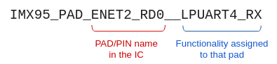
From left to right, the first part of the macro after the |
The IMX95_PAD_ENET2_RD0__LPUART4_RX macro defined in arch/arm64/boot/dts/freescale/imx95-pinfunc.h contains five integers:
#define IMX95_PAD_ENET2_RD0__LPUART4_RX 0x0118 0x031C 0x0564 0x01 0x00These five integers are:
-
IOMUX register offset (
0x0118) -
Pad configuration register offset (
0x031C) -
Select input daisy chain register offset (
0x0564) -
IOMUX configuration setting (
0x01) -
Select input daisy chain setting (
0x00)
The sixth integer, 0x31e, corresponds to the configuration for the PAD control register.
This number defines the low-level physical settings of the pin, such as whether it has an internal pull resistor, or the drive strength.
Refer to the NXP i.MX95 Hardware Reference Manual for information on pad settings.
Configure independent pin IOMUX and pad control
You may want to configure an IOMUX setting that is not associated with a specific device driver.
An example of this would be a GPIO connected to a push button, LED, or control lines of devices that do not have a binding on their drivers.
For that purpose you can define generic pinctrl-0 property inside the iomuxc node:
&iomuxc {
	pinctrl-names = "default";
	pinctrl-0 = <&pinctrl_gpio>;

	[...]

	/* GPIOs for User Leds, Buttons, ... */
	pinctrl_gpio: gpiogrp {
		fsl,pins = <
			/* ULED/BUTTON1 */
			IMX95_PAD_GPIO_IO32__GPIO5_IO_BIT12		0x31e
		>;
	};

	[...]
};| Do not configure the same pad twice in the device tree. IOMUX configurations are set by the drivers in the order the kernel probes the configured device. If the same pad is configured differently by two drivers, the settings associated with the last-probed driver will fail to apply and the driver will not be brought up. |
