

The NXP i.MX95 CPU has five GPIO ports. The number of GPIOs that each port can generate and control varies:
-
GPIO1: 16 signals
-
GPIO2: 32 signals
-
GPIO3: 32 signals
-
GPIO4: 30 signals
-
GPIO5: 18 signals
GPIOs on the ConnectCore 95 platforms
On the ConnectCore 95 SMT SOM:
-
Many of the i.MX95 GPIOs are available on the system-on-module, multiplexed with other functions (labeled GPIOx_IO_BITy where x is the port and y is the GPIO pin). See Hardware reference manuals for information about GPIO pins and their multiplexed functionality.
On the ConnectCore 95 SMARC SOM:
-
Many of the i.MX95 GPIOs are available on the SMARC connector, multiplexed with other functions.
-
The MCA on the ConnectCore 95 SMARC SOM provides 29 additional GPIOs, some of which are used internally and some of which are routed to the the SMARC connector. See MCA I/O pads for a list of all available MCA IOs and their capabilities.
On the ConnectCore 95 Development Kit:
The expansion connectors allow direct access to some of the GPIOs.
GPIOs on the SOM and carrier board are used for many purposes, such as:
-
Power enable line for transceivers
-
Reset line for controllers
-
Interrupt line
-
User LED
-
User button
| This topic focuses on the i.MX95 GPIOs. For information on MCA GPIOs refer to MCA General Purpose Input/Output (GPIO). |
Kernel configuration
Support for i.MX95 GPIOs is automatically provided through the non-visible option CONFIG_GPIO_VF610.
Kernel driver
The driver for the i.MX95 GPIO is located at:
| File | Description |
|---|---|
i.MX95 GPIO driver |
Device tree bindings and customization
The i.MX95 GPIO device tree binding is documented at
Documentation/devicetree/bindings/gpio/gpio-vf610.yaml.
One GPIO controller is defined for each i.MX95 GPIO port in the common i.MX95 device tree file:
	gpio1: gpio@47400000 {
		compatible = "fsl,imx95-gpio", "fsl,imx8ulp-gpio";
		reg = <0x47400000 0x1000>;
		gpio-controller;
		#gpio-cells = <2>;
		interrupts = <GIC_SPI 10 IRQ_TYPE_LEVEL_HIGH>,
				<GIC_SPI 11 IRQ_TYPE_LEVEL_HIGH>;
		interrupt-controller;
		#interrupt-cells = <2>;
		clocks = <&scmi_clk IMX95_CLK_M33>,
				<&scmi_clk IMX95_CLK_M33>;
		clock-names = "gpio", "port";
		gpio-ranges = <&scmi_iomuxc 0 112 16>;
		npgios = <16>;
	};

	[...]

	gpio5: gpio@43850000 {
		compatible = "fsl,imx95-gpio", "fsl,imx8ulp-gpio";
		reg = <0x0 0x43850000 0x0 0x1000>;
		gpio-controller;
		#gpio-cells = <2>;
		interrupts = <GIC_SPI 55 IRQ_TYPE_LEVEL_HIGH>,
				<GIC_SPI 56 IRQ_TYPE_LEVEL_HIGH>;
		interrupt-controller;
		#interrupt-cells = <2>;
		clocks = <&scmi_clk IMX95_CLK_BUSWAKEUP>,
				<&scmi_clk IMX95_CLK_BUSWAKEUP>;
		clock-names = "gpio", "port";
		gpio-ranges = <&scmi_iomuxc 0 92 12>, <&scmi_iomuxc 12 36 6>;
		ngpios = <18>;
	};
For example, on the ConnectCore 95 Development Kit, GPIO1_IO8 is used as the HDMI hotplug detect line:
hdmi-connector {
compatible = "hdmi-connector";
pinctrl-names = "default";
pinctrl-0 = <&pinctrl_hdmi_hpd>;
hdmi-pwr-supply = <®_5v_board>;
hpd-gpios = <&gpio1 8 GPIO_ACTIVE_HIGH>;
ddc-i2c-bus = <&lpi2c2>;
label = "hdmi";
type = "a";
port {
hdmi_connector_in: endpoint {
remote-endpoint = <<8912_out>;
};
};
};IOMUX configuration
You must configure the pads that are to be used as i.MX95 GPIOs. See Pin multiplexing (IOMUX).
For GPIOs that are managed by other drivers, you must configure their pad IOMUX inside the driver node specific pinctrl-N to work as GPIO.
For GPIOs that are not associated with any interface or that can’t be handled by a driver, see Configure independent pin IOMUX and pad control.
GPIO pads power domains
The i.MX95 GPIOs may work at 1.8 V or 3.3 V depending on the power domain of the pad they are on. To determine the working voltage of a given GPIO:
-
Locate the pad of a given signal on the ConnectCore 95 Development Kit schematics. For instance, on the ConnectCore 95 Development Kit, signal
CAN2_STBcomes from padSPI1_SCK(pad AE1) of the ConnectCore 95 SOM: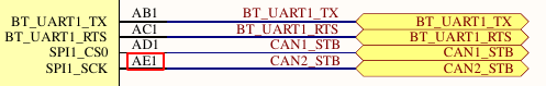
-
Locate this pad on the IOMUX section of the ConnectCore 95 Hardware Reference Manual. This table lists the associated GPIO of the pad, and the power domain it is on:
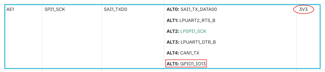
-
In the example, the power domain is 3V3. If a different power domain applies, locate it on the ConnectCore 95 Development Kit schematics to determine its voltage.
Use the GPIOs
The package libgpiod (added by packagegroup-dey-core) provides a set of tools (such as gpioget, gpioset, etc.) for controlling the GPIOs from user space.
| You can still control the GPIOs from the sysfs, but this API is not recommended. See https://www.kernel.org/doc/html/latest/userspace-api/gpio/sysfs.html. |
Detect GPIO ports
Use gpiodetect to list the GPIO ports detected by the kernel:
# gpiodetect
gpiochip0 [43810000.gpio] (32 lines)
gpiochip1 [43820000.gpio] (32 lines)
gpiochip2 [43840000.gpio] (30 lines)
gpiochip3 [43850000.gpio] (18 lines)
gpiochip4 [47400000.gpio] (16 lines)
gpiochip5 [mca-gpio] (29 lines)
where:
-
Ports
gpiochip0togpiochip4are the i.MX95 GPIO ports. This nomenclature corresponds with GPIO2 to GPIO5 and GPIO1, as shown in the i.MX95 reference manual. -
Port
gpiochip5is the MCA GPIO port.
| GPIO1 port belongs to the Always-ON (AON) domain and is probed after ports GPIO2..GPIO5. |
Information about a GPIO port
Use gpioinfo to list the lines of a given port:
# gpioinfo gpiochip4
gpiochip4 - 16 lines:
        line   0:      unnamed       unused   input  active-high
        line   1:      unnamed       unused   input  active-high
        line   2:      unnamed       unused   input  active-high
        line   3:      unnamed       unused   input  active-high
        line   4:      unnamed       unused   input  active-high
        line   5:      unnamed       unused   input  active-high
        line   6:      unnamed       unused   input  active-high
        line   7:      unnamed       unused   input  active-high
        line   8:      unnamed        "hpd"   input  active-high [used]
        line   9:      unnamed   "spi0 CS1"  output   active-low [used]
        line  10:      unnamed  "interrupt"   input  active-high [used]
        line  11:      unnamed   "spi0 CS0"  output   active-low [used]
        line  12:      unnamed       unused   input  active-high
        line  13:      unnamed       unused   input  active-high
        line  14:      unnamed       unused   input  active-high
        line  15:      unnamed       unused   input  active-high
Set an output high/low
Use gpioset to set a i.MX95 GPIO as output, such as GPIO1_IO27.
Use =1 to set it high, or =0 to set it low:
# gpioset gpiochip1 27=1
# gpioset gpiochip1 27=0
Read an input
Use gpioget to read the value of a i.MX95 GPIO input, such as GPIO1_IO27:
# gpioget gpiochip1 27
0
Use a GPIO as interrupt
Use gpiomon to wait for an event on a given GPIO, such as GPIO1_IO27:
# gpiomon --num-events 1 --rising-edge gpiochip1 27See the libgpiod documentation for more information on these tools.
Sample application
An example application called apix-gpio-example is included in the dey-examples-digiapix recipe (part of dey-examples package) of the meta-digi layer.
This application shows how to manage GPIO lines using the Digi APIx library on the ConnectCore 95 platform.
|
By default, the Get Started with ConnectCore Cloud Services demo application seizes the user button.
To use the example, stop the |
Go to GitHub to see the application instructions and source code.
See GPIO API for more information about the GPIO APIx.
