

The STM32MP25 SOC platform includes a low-power Cortex-M33 processor with a low gate count and low interrupt latency. The Cortex-M33 implements the ARMv8-M instruction set architecture (ISA) and adds significant capabilities with digital signal processor (DSP) and single instruction multiple data (SIMD) extensions. The Cortex-M33 operates as a coprocessor, either autonomously as any external microcontroller, or by communicating with the main processor (Cortex-A35) via the RPMsg communication pipe.
STMicroelectronics provides an integrated development environment (IDE) for developing and debugging CortexM applications.
|
The pinout on ConnectCore MP25 Development Kit DVK versions 1-4 is mirrored compared to standard pinout. For these boards, you must create a custom adapter to connect the debugger. To find out which board version you have, refer to Carrier board version and ID. Mirrored header pinout requiring custom adapter 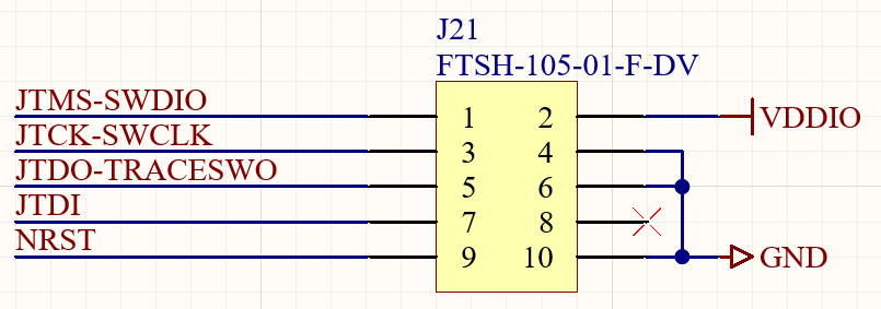
Standard header pinout 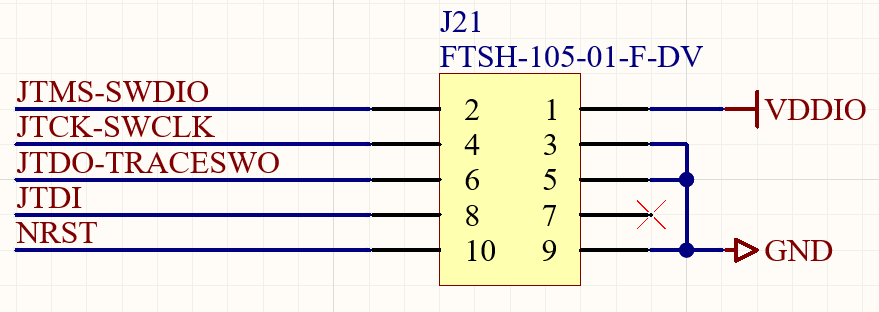
|
1. Develop and build firmware for the Cortex-M33
To develop and build firmware for the Cortex-M33, follow the instructions in the STM32MP25 Getting Started guide to:
-
Download and install the STM32CubeIDE
-
Install the STM32Cube MPx package
-
Create and build a firmware project
| The example applications included in the STM32CubeIDE may use peripherals, such as GPIOs or ADC lines, available on STM evaluation boards. You may need to adapt the source code to lines and peripherals that are available on the ConnectCore MP25 Development Kit. |
2. Deploy the firmware onto the target
Choose one of the following ways to deploy the firmware onto the Cortex-M33:
Run your firmware application with Remoteproc from Linux
The remote processor (RPROC) framework allows the different platforms/architectures to control (power on, load firmware, power off) remote processors while abstracting the hardware differences. The application must either be stored on a partition of an external device or included in the rootfs image.
-
Locate the built firmware file (
.elf). This is located in your project folder, under a path such as<yourproject>/STM32CubeIDE/CM33/NonSecure/Debug. -
Copy the firmware from the host to the target inside
/lib/firmware, for instance over SSH:$ scp <firmware-file.elf> root@<device-ip>:/lib/firmware -
To load the firmware on the Cortex-M33:
# echo -n <firmware-file.elf> > /sys/class/remoteproc/remoteproc0/firmware -
To start the firmware:
# echo start > /sys/class/remoteproc/remoteproc0/state -
To check the firmware output log:
# cat /sys/kernel/debug/remoteproc/remoteproc0/trace0 -
To stop the firmware:
# echo stop > /sys/class/remoteproc/remoteproc0/state
|
Remoteproc looks for firmware files in |
Run and debug your firmware using the IDE
To run or debug the firmware from the IDE you need one of these debuggers:
Run the firmware
The following instructions show how to download the firmware to your device and run it:
-
Connect the ST-LINK debugger to your development computer. This is required by the IDE, but you don’t need to connect it to the device. The firmware is transferred via Ethernet.
-
Start the STM32CubeIDE.
-
Select your Cortex-M33 project.
-
Right click the project and select Run As > Run configurations. This opens the Run configuration panel.
-
If not already created, create your run configuration by clicking on the STM32 C/C++ Application.
-
In the C/C++ Application box click on the Search Project.. button and select the ELF file you want to debug.
-
On the Debugger tab:
-
Select thru Linuxcore (Production mode).
-
Select the ST-Link serial port available on the Serial Port. The IDE automatically detects ST-Link serial port.
-
Set the IP address of your target in the Inet Address field. The IDE will create a SSH connection to the target for the firmware download.
-
-
Click Apply and Run.
This loads the firmware on the target and runs it.
Debug the firmware
-
Connect the ST-LINK debugger to your development computer and to the CPU JTAG connector (
J21) on the ConnectCore MP25 Development Kit. (The connector is not populated by default.) -
Start the STM32CubeIDE.
-
Select your Cortex-M33 project.
-
Right click the project and select Debug As > Debug configurations. This opens the Debug configuration panel.
-
If not already created, create your debug configuration by clicking on the STM32 C/C++ Application.
-
On the Debugger tab:
-
Select thru Linuxcore (Production mode).
-
Select the ST-Link serial port available on the Serial Port. The IDE automatically detects ST-Link serial port.
-
Set the IP address of your target in the Inet Address field. The IDE will create a SSH connection to the target for the firmware download.
-
-
Click Apply and Debug.
This loads the firmware on the target, runs it and opens the debug perspective. You can press Suspend to stop the firmware.
| For the best GDB debug experience, Digi recommends you upgrade the onboard ST-Link version with the latest release by going to Help > ST-Link Upgrade in the STM32CubeIDE menu. |
For more information, refer to the STM32CubeIDE documentation.
Boot your firmware from U-Boot
You can load and start the firmware application from U-Boot with the rproc command.
-
Transfer the firmware to the target RAM address, for instance if the firmware is on a USB stick:
=> usb start => load usb 0:1 ${loadaddr} <firmware-file.elf> -
Initialize rproc and load the firmware from RAM
=> rproc init => rproc load 0 ${loadaddr} ${filesize} -
Start the firmware:
=> rproc start 0
Protect the Cortex-M33 coprocessor firmware
You can protect Cortex-M33 firmware by using secure OTP keys together with image signing and encryption. When enabling TrustFence, Digi Embedded Yocto generates a default PKI tree that includes the keys needed to sign and encrypt the Cortex-M33 firmware. For additional details on TrustFence keys, see Summary of TrustFence keys.
When TrustFence support is enabled, Digi Embedded Yocto automatically adds support to authenticate the Cortex-M33 coprocessor firmware.
On your Linux system, you can verify whether RemoteProc accepts ELF (unsigned ELF image) or TEE (signed image) formats:
# cat /sys/class/remoteproc/remoteproc0/fw_format
TEE
If TEE appears, only signed firmware is supported; if ELF appears, unsigned ELF images are accepted.
|
To sign the RPROC firmware you need to install the Digi Embedded Yocto toolchain. See Install toolchains for more information. |
Follow these instructions to manually sign and encrypt your Cortex-M33 coprocessor firmware:
-
Set up the toolchain environment:
$ . environment-setup-cortexa35-dey-linux -
Install the following Python libraries required by the signing script:
$ pip install pyelftools pycryptodomex -
Run the Python RPROC sign script with these arguments:
$ python3 $TA_DEV_KIT_DIR/scripts/sign_rproc_fw.py \
    --in <input-file>
    --out <output-file>
    --key <private-key-file>
    --key_pwd <private-key-password>
    --key_type=ECC \
    --key_info <public-key-info-file>
    --enc_key <encryption-key-file>
    --plat-tlv BOOTADDR 0x80100000
where:
-
<input-file>is the firmware binary to sign (in ELF format) -
<output-file>is the signed and encrypted binary generated by the script -
<private-key-file>path to the PEM private key for the signature -
<private-key-password>password of the private key if the key is protected -
<public-key-info-file>path to the public key in DER format -
<encryption-key-file>path to the encryption key for firmware image encryption (optional) -
<boot address>boot address that must correspond to the vector table in memoryDigi recommends using the stripped elf binary to avoid including debug information, non-essential symbols, and comments. For example (considering key files on
trustfence/folder of your project):$ python3 $TA_DEV_KIT_DIR/scripts/sign_rproc_fw.py \ --in my-rproc-fw-stripped.elf \ --out my-rproc-fw-signed-encrypted.bin \ --key trustfence/rproc-keys/privateKey.pem \ --key_pwd my-private-key-password-in-plain-text \ --key_type=ECC \ --key_info trustfence/rproc-keys/publicKey.der \ --enc_key trustfence/encryption_key_rproc.bin \ --plat-tlv BOOTADDR 0x80100000
-
-
Load the signed firmware onto the target:
The process to run the signed firmware on the Cortex-M33 is the same as described previously in Deploy the firmware onto the target.
Next steps
You can use the EVK Template included in the installed SDK as a starting point for a Cortex-M33 firmware application.
