

The NXP {cpu-family} CPU has five GPIO ports. Each port can generate and control 32 signals.
The MCA also features a number of GPIO pins (multiplexed with Analog-to-Digital Converter (ADC) functionality). See MCA I/O pads for a list of all available MCA IOs and their capabilities.
GPIOs on the ConnectCore 8M Nano platforms
-
On the ConnectCore 8M Nano system-on-module:
-
Many of the {cpu-family} GPIOs are available at the system-on-module, multiplexed with other functions (labeled GPIOx_IOy where x is the port and y is the GPIO pin). See Hardware reference manuals for information about GPIO pins and their multiplexed functionality.
-
15 MCA GPIO pins are available (labeled MCA_IOx where x is the GPIO pin).
-
-
On the ConnectCore 8M Nano Development Kit, the expansion connectors allow direct access to some of the {cpu-family} GPIOs.
GPIOs on the SOM and carrier board are used for many purposes, such as:
-
Power enable line for transceivers
-
Reset line for controllers
-
LCD backlight control
-
Interrupt line
-
User LED
-
User button
Kernel configuration
Support for {cpu-family} GPIOs is automatically provided through the non-visible option CONFIG_GPIO_MXC.
Kernel driver
The driver for the {cpu-family} GPIO is located at:
| File | Description |
|---|---|
{cpu-family} GPIO driver |
Device tree bindings and customization
The {cpu-family} GPIO device tree binding is documented at
Documentation/devicetree/bindings/gpio/fsl-imx-gpio.txt.
One GPIO controller is defined for each {cpu-family} GPIO port in the common {cpu-family} device tree file:
	gpio1: gpio@30200000 {
		compatible = "fsl,imx8mm-gpio", "fsl,imx35-gpio";
		reg = <0x0 0x30200000 0x0 0x10000>;
		interrupts = <GIC_SPI 64 IRQ_TYPE_LEVEL_HIGH>,
			     <GIC_SPI 65 IRQ_TYPE_LEVEL_HIGH>;
		gpio-controller;
		#gpio-cells = <2>;
		interrupt-controller;
		#interrupt-cells = <2>;
	};

[...]

	gpio5: gpio@30240000 {
		compatible = "fsl,imx8mm-gpio", "fsl,imx35-gpio";
		reg = <0x0 0x30240000 0x0 0x10000>;
		interrupts = <GIC_SPI 72 IRQ_TYPE_LEVEL_HIGH>,
			     <GIC_SPI 73 IRQ_TYPE_LEVEL_HIGH>;
		gpio-controller;
		#gpio-cells = <2>;
		interrupt-controller;
		#interrupt-cells = <2>;
	};
The ConnectCore 8M Nano device tree include file and the carrier board device tree files use the {cpu-family} GPIOs.
For example, on the ConnectCore 8M Nano, GPIO3_IO08 is used as the MCA interrupt line, and GPIO1_IO4 is used to activate internal circuitry during the MCA firmware update:
	mca_cc8m: mca@63 {
		compatible = "digi,mca-cc8m";
		reg = <0x63>;
		interrupt-parent = <&gpio2>;
		interrupts = <10 IRQ_TYPE_LEVEL_HIGH>;
		interrupt-controller;
		#interrupt-cells = <2>;
		fw-update-gpio = <&gpio1 5 GPIO_ACTIVE_LOW>;
		pinctrl-names = "default";
		pinctrl-0 = <&pinctrl_mca_cc8m>;

		[...]
};
For example, on the ConnectCore 8M Nano Development Kit, GPIO5_IO3 is used to reset the PHY of ENET1 Ethernet interface:
&fec1 {
pinctrl-names = "default";
pinctrl-0 = <&pinctrl_fec1_gpio>,
<&pinctrl_fec1>;
phy-mode = "rgmii-id";
phy-handle = <ðphy0>;
digi,mdio-lt-supply = <®_1v8_ext>;
phy-supply = <®_3v3_eth0>;
phy-reset-gpios = <&gpio5 3 GPIO_ACTIVE_LOW>;
phy-reset-duration = <1>;
digi,phy-reset-in-suspend;
fsl,magic-packet;
status = "okay";
[...]
};IOMUX configuration
You must configure the pads that are to be used as {cpu-family} GPIOs. See Pin multiplexing (IOMUX).
For GPIOs that are managed by other drivers, you must configure their pad IOMUX inside the driver node specific pinctrl-0 to work according to the specified interface functionalities.
On the ConnectCore 8M Nano example from above, mca_cc8m node configures pinctrl_mca_cc8m:
pinctrl_mca_cc8m: mcagrp {
	fsl,pins = <
		/* MCA_nINT */
		MX8MN_IOMUXC_SD1_RESET_B_GPIO2_IO10	0x56
		/* MCA_FW_UPDATE */
		MX8MN_IOMUXC_GPIO1_IO05_GPIO1_IO5	0x16
	>;
};
For GPIOs that are not associated with any interface or that can’t be handled by a driver, see Configure independent pin IOMUX and pad control. The following external pads are configured as GPIOs on the default device tree:
-
On the ConnectCore 8M Nano Development Kit J46 expansion connector:
Pad Signal GPIO 3
GPIO1_IO10
GPIO1_IO10
4
GPIO1_IO15
GPIO1_IO15
5
GPIO1_IO11
GPIO1_IO11
7
GPIO1_IO13
GPIO1_IO13
9
GPIO1_IO14
GPIO1_IO14
-
On the ConnectCore 8M Nano Development Kit J48 expansion connector:
Pad Signal GPIO 5
EXP_I2C_IRQ_N
GPIO5_IO27
7
EXP_I2C_GPIO
GPIO5_IO26
-
User LED 3 is GPIO2_IO19
-
User button 2 is GPIO2_IO20
GPIO pads power domains
The {cpu-family} GPIOs are configurable and can work at 1.8 V or 3.3 V depending on the power domain of the pad they are on.
To determine the working voltage of a given GPIO:
-
Locate the pad of a given signal on the ConnectCore 8M Nano Development Kit schematics. For instance, on the ConnectCore 8M Nano Development Kit, signal
UART4_TXcomes from padUART4_TXDof the ConnectCore 8M Nano SOM: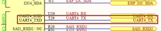
-
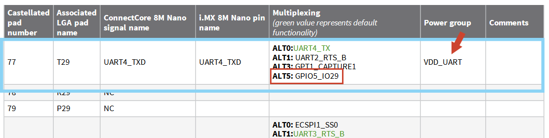
Locate this pad on the IMOUX section of the ConnectCore 8M Nano Hardware Reference Manual. This table lists the associated GPIO of the pad, and the power domain it is on:
-
Locate the power domain (
VDD_UARTon the example) on the ConnectCore 8M Nano Development Kit schematics. Here you can tell the voltage of the power domain: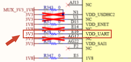
Using the GPIOs
The package libgpiod (added by packagegroup-dey-core) provides a set of tools (such as gpioget, gpioget, etc.) for controlling the GPIOs from user space.
| You can still control the GPIOs from the sysfs, but this ABI is not recommended. See https://www.kernel.org/doc/html/latest/admin-guide/gpio/sysfs.html. |
Detect GPIO ports
Use gpiodetect to list the GPIO ports detected by the kernel:
# gpiodetect
gpiochip0 [gpio1] (32 lines)
gpiochip1 [gpio2] (32 lines)
gpiochip2 [gpio3] (32 lines)
gpiochip3 [gpio4] (32 lines)
gpiochip4 [gpio5] (32 lines)
gpiochip5 [mca-gpio] (19 lines)
gpiochip6 [spi2.0] (2 lines)
where:
-
Ports
gpio1togpio5are the {cpu-family} GPIO ports. -
Port
mca-gpiois the MCA GPIO port. -
Port
spi2.0is the external CAN controller on the ConnectCore 8M Nano Development Kit.
Information about a GPIO port
Use gpioinfo to list the lines of a given port:
# gpioinfo gpio1
gpiochip0 - 32 lines:
	line   0:      unnamed       unused   input  active-high
	line   1:      unnamed       unused   input  active-high
	line   2:      unnamed       unused   input  active-high
	line   3:      unnamed        "rts"  output  active-high [used]
	line   4:      unnamed       unused   input  active-high
	line   5:      unnamed "mca-fw-update" output active-high [used]
	line   6:      unnamed "regulators:regulator@4" output active-high [used]
	line   7:      unnamed       unused  output  active-high
	line   8:      unnamed       unused  output  active-high
	line   9:      unnamed       unused   input  active-high
	line  10:      unnamed       unused   input  active-high
	line  11:      unnamed       unused   input  active-high
	line  12:      unnamed       unused  output  active-high
	line  13:      unnamed       unused   input  active-high
	line  14:      unnamed       unused   input  active-high
	line  15:      unnamed       unused   input  active-high
	line  16:      unnamed       unused   input  active-high
	line  17:      unnamed       unused   input  active-high
	line  18:      unnamed       unused   input  active-high
	line  19:      unnamed       unused   input  active-high
	line  20:      unnamed       unused   input  active-high
	line  21:      unnamed       unused   input  active-high
	line  22:      unnamed       unused   input  active-high
	line  23:      unnamed       unused   input  active-high
	line  24:      unnamed       unused   input  active-high
	line  25:      unnamed       unused   input  active-high
	line  26:      unnamed       unused   input  active-high
	line  27:      unnamed       unused   input  active-high
	line  28:      unnamed       unused   input  active-high
	line  29:      unnamed       unused   input  active-high
	line  30:      unnamed       unused   input  active-high
	line  31:      unnamed       unused   input  active-high
Set an output high/low
Use gpioset to set a {cpu-family} GPIO as output, such as GPIO5_IO27.
Use =1 to set it high, or =0 to set it low:
# gpioset gpio5 27=1
# gpioset gpio5 27=0
Read an input
Use gpioget to read the value of a {cpu-family} GPIO input, such as GPIO5_IO27:
# gpioget gpio5 27
0
Use a GPIO as interrupt
Use gpiomon to wait for an event on a given GPIO, such as GPIO5_IO27:
# gpiomon --num-events 1 --rising-edge gpio5 27See the README of libgpiod for more information on the usage of these tools.
Sample application
An example application called apix-gpio-example is included in the dey-examples-digiapix recipe (part of dey-examples package) of meta-digi layer.
This application shows how to manage GPIO lines using the Digi APIx library on the ConnectCore 8M Nano platform.
Go to GitHub to see the application instructions and source code.
See GPIO API for more information about the GPIO APIx.
See MCA General Purpose Input/Output (GPIO) for additional information on MCA GPIOs.
