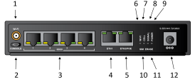
Front panel and LEDs
| Item | Name | Description |
|---|---|---|
| 1 | Wi-Fi |
Connect a Wi-Fi antenna to the device. For connection instructions, see Connect the Wi-Fi antenna. |
| 2 | Console |
Use the USB console port to access the web UI on the device if a network is not available. For example, you can use a micro USB cable to connect the device to your laptop and then find the IP address for the device. See Discover the IP address using a Micro USB cable. |
| 3 | Serial ports 1-4 |
Use the serial ports to connect to devices and equipment to the Connect EZ 4/4i. See Connect equipment to the Connect EZ serial port. The serial port LED shows the status of the connection.
|
| 4 | ETH1 |
Use the ETH1 port to connect the device to your local network, using an Ethernet cable. The ETH1 LED shows the status of the connection.
|
| 5 | ETH2 |
Use the ETH2 port to connect to a second Ethernet port. This is useful for redundancy or if you have more than one network. The ETH2 LED shows the status of the connection.
|
| 5 | ETH2/POE |
For Connect EZ 4 with PoE (EZ04-P000) only For the Connect EZ 4 with PoE variant, you can use ETH2/POE as a second Ethernet port, or as a remote power point, by connecting a 802.3af PoE PSE (power source) to the port. Note The Connect EZ 4 with PoE will not draw more than 15 W from the PoE supply. This device meets the IEEE 802.3af PoE standard. |
| 6 | Wi-Fi LED |
Shows the status of the Wi-Fi connection. For more information, see Wi-Fi LED descriptions for more information. |
| 7 | Cell LED |
Shows the status of the cell service connection. The Cell and Signal LEDs work together to display some status information. See Cell service and signal LED descriptions. |
| 8 | Signal LED |
Shows the strength of the cellular signal. The Cell and Signal LEDs work together to display some status information. See Cell service and signal LED descriptions. |
|
9 |
Power LED |
The Power LED shows the status of the power supply connection.
|
| 10 | SIM switch button |
The SIM switch button is used to manually toggle between the two SIM slots included in the Digi CORE Module. For information about using this feature, see Switch the SIM card used for cellular network connection. Note This feature is useful only if you have connected the Digi CORE module. See Create a cellular connection using the CORE module. |
| 11 | Erase button |
Use this button to reset the device to factory defaults. You need to use a pinhole tool to press the button. |
| 12 | Power |
Connect the power supply. See Connect the power supply. |
Wi-Fi LED descriptions
| Wi-Fi LED | Description | |
|---|---|---|
| Off | Both the access point and Wi-Fi client are unconfigured. | |
| Solid green | Client is connected. (No access point.) | |
| Flash green | Client is searching for connection. (No Access P0int.) | |
| Solid amber | Client is unconfigured. Access point is up. | |
| Solid blue | Client is connected. Access point is up. | |
| Flashing amber/green | Client is searching. Access point is up. | |
| Solid red | An error has occurred. | |
Cell service and signal LED descriptions
| Cell LED | Signal LED | Description |
|---|---|---|
| Slow flash red | Slow flash red | Updating modem firmware |
| Slow flash green | Slow flash green | Recovering modem firmware |
| Slow flash green | Off | Waiting for modem to appear |
| Off | Off | Modem not present |
| Fast flash red | Off | SIM not present |
| Off | Solid blue | Modem signal strength: 5 bars |
| Off | Solid green | Modem signal strength: 4 bars |
| Off | Solid amber | Modem signal strength: 3 bars |
| Off | Solid red | Modem signal strength: 2 bars |
| Off | Slow flash red | Modem signal strength: 1 bars |
| Off | Fast flash red | Modem signal strength: 0 bars |
| Off | Off | Modem signal strength: * |
| Solid amber | Off | Cell service: 2G |
| Solid green | Off | Cell service: 3G |
| Solid blue | Off | Cell service: 4G |
| Off | Off | Cell service: None |
 PDF
PDF


