Front panel and LEDs
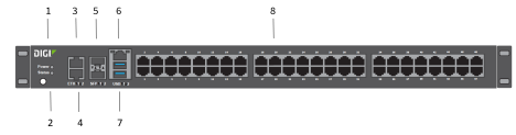
| Item | Name | Description |
|---|---|---|
|
1 |
Power |
The LED lights up when the power is supplied to the device and the device powered on.
|
|
2 |
The LED lights up when the Connect IT starts up or you have activated the Find Me feature.
|
|
|
3 |
ETH2 |
Indicates the status of the backup connection on the LAN. ETH2 is configured for LAN/DHCP server. See Connect to a site network using an Ethernet LAN. The LED indicates the connection status:
|
|
4 |
ETH1 |
Indicates connection to Ethernet WAN network. ETH1 is configured for WAN/DHCP client. |
|
5 |
SFP1 SFP2 |
Two SFP+ ports are available.
Note The SFP+ hardware must be purchased separately. To use this feature you must do both steps:
Note When you use an SFP+ module, you cannot use the equivalent Ethernet port. For example, if you insert an SFP+ module into the SFP1 slot, you cannot use the ETH1 slot. If you insert an SFP+ module into the SFP2 slot, you cannot use the ETH2 slot. The SFP+ LED indicates the connection status.
|
|
6 |
Connect a computer to the Connect IT. This enables you to log into the Connect IT if a network is not available. See Log into the Connect IT from the Console port.
|
|
|
7 |
USB ports |
Connect a USB flash drive to the Connect IT for backup or logging. |
|
8 |
Serial ports |
Connect equipment to a serial port to provide console access to the equipment through the cellular network. See Connect equipment to the Connect IT serial ports.
The LED on the left lights:
The LED on the right for ACT lights yellow. |
 PDF
PDF


