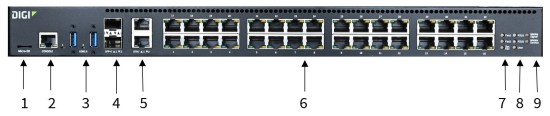
Front panel and LEDs
| Item | Name | Description |
|---|---|---|
| 1 | Micro-SD | Insert an SD card. |
| 2 | Console |
Connect the RJ45F to DB9F RS232 console adapter to the Console port. |
| 3 |
USB 3.0 1 USB 3.0 2 |
The two USB ports act as an AnywhereUSB 2 Plus Hub. The USB ports can only be used in conjunction with the AnywhereUSB Manager, which must be installed separately. You can use the AnywhereUSB Manager connect to and monitor the devices connected to the USB ports. You can configure the AnywhereUSB service and AnywhereUSB Manager from the Connect EZ 16/32 web UI. See AnywhereUSB 2 Plus USB ports on a Connect EZ 16/32. Note The USB Implementers Forum (USB-IF) renamed USB 3.0 to USB 3.1 Gen 1. There is no change in performance, functionality, or electrical characteristics between USB 3.0 and USB 3.1 Gen 1. |
| 4 |
SFP+ 1 SFP+ 2 |
Connect an SFP+ transceiver module for fiber connection, such as Finisar Network FTLX8574D3BCL SFP+. For more information, see Configure an SFP+ port. Note Connect EZ 16/32 can support both a copper port and an SFP+ port at the same time. If an SFP+ port is enabled, the SFP+ port LED will illuminate if an SPF+ transceiver is installed, regardless of whether the optical/fiber cable is connected end-to-end. |
| 5 | ETH 1 |
Use the ETH 1 port to connect the device to your local network using an Ethernet cable. See Connect to site network using an Ethernet LAN. The ETH 1 LED shows the status of the connection.
|
| 5 | ETH 2 |
Use the ETH 2 port to connect to a second Ethernet port. This is useful for redundancy or if you have more than one network. The ETH 2 LED shows the status of the connection.
|
| 6 |
Serial ports 1-16 OR 1-32 |
Use the serial ports to connect to devices and equipment to the Connect EZ 16/32. See Connect equipment to the Connect EZ serial port. The serial port LED shows the status of the connection.
|
| 7 |
Fan1 LED |
The LED shows the status of Fan1 that is included with PSU1, which is on the right side of the back of the device. Solid green: The fan is running within normal range of use. Solid red: The fan slows down or the device is overheating. |
| 7 |
Fan2 LED |
The LED shows the status of Fan2 that is included with PSU2, which is on the lft side of the back of the device.
|
| 7 |
Sys. Fan LED |
The LED shows the status of Sys. Fan, which is the fan on the back of the device that is not associated with a PSU (power supply unit).
|
| 8 |
PSU1 LED |
The LED shows the status of power supply and fan unit on the left. This power supply and fan unit is factory-installed.
|
| 8 |
PSU2 LED |
The LED shows the status of power supply and fan unit on the right. This power supply and fan unit is optional.
|
| 8 |
User LED |
LED used for the Find Me feature. When this feature is activated, the LED blinks orange and then green. |
| 9 |
WWAN Signal LED |
Shows the strength of the WWAN signal. |
| 9 |
WWAN Service LED |
Shows the status of the WWAN service. |
 PDF
PDF


