Configure a hex input pin on a Connect Sensor XRT-M
You can configure an input source for hex data.
-
 Navigate to the Input Configuration page.
-
From the Options section, click Applications. The Available Applications page displays.
-
Click Automation Control. The Management & Administration page displays.
-
Click Inputs. The Input Configuration page displays.
-
-
In the Input Type column, click on a Disabled button.
Note An input pin with an input type other than Disabled has already been configured and can be updated.
-
At the top of the page, click Hex.
-
Configure the settings as described in the tables below.
Hex Input Source
Item Description Select an input source option.
-
Configured Inputs: Select an input pin.
-
Configured Outputs: Select an output pin.
-
System Variables: Select a standard data option.
-
Industrial Protocols
General Pin Options
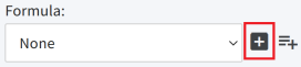
Item Description Formula
(Optional) Select an existing formula from the Formula list box.
When data is received from the input source, the formula is run, and the result is the output value for this source.
You can create a formula from this page if needed.
-
Add Device Formula: Click the plus icon to display the Add Formula page so you can create a formula for this device.
-
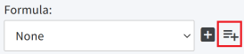
Add Device Group Formula: Click the plus with lines icon to the display the Add Device Group Formula page so you can create a formula that can be used by the devices in a specified device group.
Display Options
Item Description Input Name
Enter a descriptive name for in the input source. The name should be unique.
Unit of Measure
Enter the unit of measurement that describes what you are measuring, such as height, volume, or pressure. This is a label that displays in Digi Axess.
Display Group
Select a display group in which this input source will be included. A display group is used to group similar devices together for easy comparison.
The options in the Display Group list box are defined in the Dashboard Settings page.
If you choose Disabled, the input source is not included in a display group.
Display Value
Select the label(s) for this input source that should display within Digi Axess.
-
Input Source: Display only the Input Name label entered in the Display Options section.
-
Threshold Alert: Display only the Threshold Alert label entered in the Thresholds section. The Threshold Alert label is available only if a threshold has been configured and then applied to this device.
-
Both: Display both the Input Name label and the Threshold Alert label.
Indicator Type
Specify whether the status of an alarm should display as a colored dot on the Device Summary page and the Automation Dashboard.
-
None: The colored dot displays in gray.
-
LED: The colored dot displays the color configured in the Alarm State list box.
-
-
Specify threshold alarms. When an alarm threshold is met, an alarm notification is sent to the specified notification group. You can create more than one threshold for an input source. A new threshold can be placed before or after an existing one, and the thresholds are numbered sequentially.
Item Description Threshold xx
(where xx is the threshold number)
From the Threshold xx list box, select a comparison option. This is used to compare a value from the input source data to the defined Trigger Value and Reset Value.
Note If Disabled is selected, this threshold alarm is not used.
Trigger Value Enter a Trigger Value that is compared to the input source value. Depending on how the threshold is configured, the following actions may occur.
-
If the comparison condition selected from the Threshold list box is met, an alarm notification is logged.
-
Send Alarm: If a notification group was selected for Send Alarm, an alarm notification is sent to the users in that group.
-
Alarm State: If an Alarm State other than None is selected, a colored alarm LED button displays within Digi Axess.
Mask Value
Enter a hexadecimal (hex) mask value that is compared to the input source value. Depending on how the threshold is configured, the following actions may occur. If the comparison condition selected from the Threshold list box is met, an alarm notification is logged.
Send Alarm: If a notification group was selected for Send Alarm, an alarm notification is sent to the users in that group.
Alarm State: If an Alarm State other than None is selected, a colored alarm LED button displays within Digi Axess.
Send Alarm Specify whether you to send an alarm to the users in a notification group when the Trigger Value is met.
-
Send an alarm notification: Select a notification group from the list box.
-
Do not send an alarm notification: Select No Alarms from the list box.
Threshold Alert
Enter a descriptive name for the alert. This label displays within Digi Axess.
Alarm State Select a color for the colored dot that displays next to the Threshold Alert label.
-
None: The dot is gray.
-
Green
-
Yellow
-
Red: The red dot blinks.
-
Blue
Options From the list box, you can choose to add another threshold alarm or delete an existing one. The threshold alarms are renumbered to be consecutive.
-
Add Below: Add a threshold alarm after the selected alarm. The threshold alarms are renumbered to be consecutive.
-
Add Above: Add a threshold alarm before the selected alarm.
-
Delete: Delete the selected threshold alarm.
-
-
Click Enable. A confirmation dialog displays.
-
Click OK. Click Back to return to the Input Configuration page.
 PDF
PDF


