Configure a digital input pin on a Connect Sensor XRT-M
You can configure an input pin for digital data.
-
 Navigate to the Input Configuration page.
-
From the Options section, click Applications. The Available Applications page displays.
-
Click Automation Control. The Management & Administration page displays.
-
Click Inputs. The Input Configuration page displays.
-
-
In the Input Type column, click on a Disabled button.
Note An input pin with an input type other than Disabled has already been configured and can be updated.
-
At the top of the page, click Digital.
-
Configure the settings as described in the tables below.
Digital Input Source
Item Description Primary Source
Select an input source option.
-
Configured Inputs: Select an input pin.
-
Configured Outputs: Select an output pin.
-
System Variables: Select a standard data option.
-
Onboard I/O
Additional Modifiers
Use the Additional Modifiers to take the value you have coming in from the pin and combine it with multiple digital inputs or outputs, outside of a formula.
-
Operation: Select AND or OR.
-
Source: Select an input source.
General Pin Options
Item Description Formula
(Optional) Select an existing formula from the Formula list box.
When data is received from the input source, the formula is run, and the result is the output value for this source.
You can create a formula from this page if needed.
-
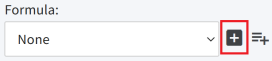
Add Device Formula: Click the plus icon to display the Add Formula page so you can create a formula for this device.
-
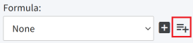
Add Device Group Formula: Click the plus with lines icon to the display the Add Device Group Formula page so you can create a formula that can be used by the devices in a specified device group.
Display Options
Item Description Input Name
Enter a descriptive name for in the input source. The name should be unique.
Display Value
Select the label(s) for this input source that should display within Digi Axess.
-
Input Source: Display only the Input Name label entered in the Display Options section.
-
Threshold Alert: Display only the Threshold Alert label entered in the Thresholds section. The Threshold Alert label is available only if a threshold has been configured and then applied to this device.
-
Both: Display both the Input Name label and the Threshold Alert label.
-
-
You can configure a threshold for the on and off states of the input pin, if needed. When a threshold is enabled and the threshold value is met, an LED button that displays next to the [ON] Label or [OFF] Label changes to the color selected from the Alarm State list box.
Alarms/Programs: OFF State Alarms
Item Description Alarms/Programs: ON State Alarms
Item Description -
Click Enable. A confirmation dialog displays.
-
Click OK. Click Back to return to the Input Configuration page.
 PDF
PDF


