set switches
Purpose
For Digi devices with Multiple Electrical Interface switch-setting capability, configures MEI settings on a per-port basis, and displays current MEI settings. MEI settings include the type of electrical interface (EIA-232 or EIA-485), the number of differential wires used for communication, and whether termination and biasing resistors are used.
MEI 232/422/485 switch settings
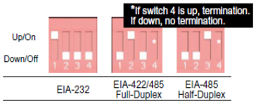
The figure shows the DIP switches that set the MEI (multiple electrical interface) line protocol on the serial interface. The table below the figure shows the direction to set the switch for each MEI function.
Note This information regarding DIP switches applies to MEI-equipped Digi devices with up to 4 ports. For MEI-equipped Digi devices with 8 or 16 ports, MEI settings can be changed through software only, using this set switches command or the web interface Configuration > Serial Ports > Multiple Electrical Interface (MEI) Serial Settings.
|
Function |
Switch Setting |
|||
|
1 |
2 |
3 |
4 |
|
|
EIA-232 |
Up/On |
Down/Off |
Down/Off |
Down/Off |
|
EIA-422/485 full-duplex |
Down/Off |
Up/On |
Down/Off |
If up, termination. If down, no termination |
|
EIA-485 half-duplex |
Down/Off |
Down/Off |
Up/On |
|
DB-9 connector and pin orientation
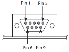
The figure shows the DB-9 pin orientation. The table shows pin signal assignments.
DB9 pinouts
|
DB-9 pin assignments |
|||
|
Pin |
EIA-232 |
EIA-422/485 |
EIA-485 |
|
1 |
DCD |
CTS- |
Not used |
|
2 |
RXD |
RXD+ |
RXD+ |
|
3 |
TXD |
TXD+ |
TXD+ |
|
4 |
DTR |
RTS- |
Not used |
|
5 |
GND |
GND |
GND |
|
6 |
DSR |
RXD- |
RXD- |
|
7 |
RTS |
RTS+ |
Not used |
|
8 |
CTS |
CTS+ |
Not used |
|
9 |
NA |
TXD- |
TXD- |
Required permissions
For Digi products with two or more users, to use this command, permissions must be set to one of the following:
- For a user to display switch settings for the line on which they are logged in: set permissions s-serial=r-self.
- For a user to display switch settings for any line: set permissions s‑serial=read.
- For a user to display and set the switch settings for the line on which they are logged in: set permissions s-serial=rw-self.
- For a user to display the switch settings for any line, and set switch settings for the line on which the user is logged in: set permissions s‑serial=w-self-r.
- For a user to display and set the switch settings on any line: set permissions s-serial=rw.
See set permissions for details on setting user permissions for commands.
Syntax
Configure MEI switches
set switches [port=range]
  [mode={232|485}]
  [wires={two|four}]
  [termination={on|off}]
Display current MEI switch settings
set switches
Options
range=range
The port or range of ports to which this command applies.
mode={232|485}
Selects the electrical interface of the serial port. The selected value determines whether the wires and termination options are meaningful.
The serial port uses electrical interface EIA-232. This interface uses independent wires to transmit and receive data, which allows data to be sent and received between devices simultaneously.
The serial port uses electrical interface EIA-485. This mode can also be used for EIA-422 connections. This interface uses either two or four wires to transmit and receive data, depending on the setting of the wires setting. This interface also allows for multiple transmitters and receivers to be easily connected together.
The wires and termination command options specifically apply to serial ports in EIA-485 mode.
The default is 232.
See Examples for information on setting and DB-9 connector and pin orientation for DB-9 connector pin orientation and pinouts.
wires={two|four}
Applies when the serial port is running in EIA-485 mode only. Selects the number of differential wires used for communication and implicitly determines the duplex of the connection.
two
The serial port operates in two-wire mode. This mode is a half-duplex connection with shared transmit and receive wires.
four
The serial port operates in four-wire mode. This mode is a full-duplex connection with independent transmit and receive pairs.
The default is four.
termination={on|off}
Applies when the serial port is running in EIA-485 mode only. Determines whether termination and biasing resistors are used across the lines.
on
Termination and biasing resistors are enabled across the lines.
Select termination to on if termination or use of biasing resistors is needed across the lines. Enable this setting if the terminal server port is an endpoint node of the EIA-422/485 network and termination or biasing is desired. If using 2-wire mode, termination or biasing is used at one of the end points; usually the Master endpoint.
Note The CTS and RTS control signals are available as separate differential signals in the EIA-422/EIA-485 4-wire mode. Do not use these differential signals in 2-wire mode. The CTS and RTS differential signals are not terminated or biased internally. If termination or biasing is needed, it must be done externally.
off
Termination and biasing resistors are disabled across the lines.
The default is off.
Examples
Configure standard EIA-232 communication
#> set switches port=1 mode=232
Configure a half-duplex EIA-485 endpoint
#> set switches port=1 mode=485 wires=two termination=on
Configure a full-duplex 422 interior node
#> set switches port=1 mode=485 wires=four termination=off
See also
- revert: The revert switches command reverts the settings configured by this command.
- set serial and the altpin={on|off} option.
- show: The show switches command shows the current MEI switch settings in a Digi device.
 PDF
PDF


